Defining magnetic field map from tabulated .txt file

Hello everyone,

I am trying to define a magnetic field within a vacuum region “DIPOLE”, the magnetic field strength values associated with each x, y, z coordinate within this region is read from a tabulated .txt file containing (X,Y,Z,BTX,BTY, BTZ,B) variables where BTX,Y, and Z are the directional cosines of the magnetic field vector. Finding different scripts I improvised and have put together a subroutine to do this (I have little to no knowledge of FORTRAN77 and minimal experience with writing subroutines for FLUKA).

In my .flair project file I have included the “MGNFIELD” card, which is left empty, is supposed to automatically call my subroutine.

At the moment the subroutine compiles successfully and there are no error messages when running the code. Hence I have no idea why the subroutine is not working, it took me a long time to get to this point but as there are no error messages I am not sure how to continue.

I have attached a sample of the tabulated .txt file I would like to read with the subroutine.

Thank you for your help!
magfldroutine.f (4.3 KB)
dipolefield3.txt (2.9 MB)

Hi Arpad,

I would tend to discourage the adoption of an user routine for this task.
On the contrary, I would exploit the (relatively) novel approach based on the magnetic field cards.
You can see the manual: 7.22.47. MGNCREATe — FLUKA Manual
A more detailed explanation is also here: https://indico.cern.ch/event/1200922/contributions/5411821/attachments/2660679/4609170/06_Magnetic_electric_fields_2023_Advanced_ANL.pdf

Starting with your case, I see that you want to perform a linear search to locate the position in the magnetic file you attached. However, your user routine contains several bugs, and the overall effect is just to return 0 in any case.

I think it is more appropiate the usage of a 3D map to model the field. To do so, you first have to create the magnetic field with an MGNCREAT card. Then, you need to provide the field in a flattened tensor containing the magnetic field components.
In easier words, given the magnetic field components (Bx, By, Bz) along the three different carthesian coordinates (x, y, z), you need to create a list of MGNDATA card:

MGNDATA   Bx(0, 0, 0) By(0, 0, 0) Bz(0, 0, 0) Bx(1, 0, 0) By(1, 0, 0) ...-> Bz(Nx, 0, 0) Bx(1, 1, 0) ..

And so on, along all the directions, as described in the manual.
What FLUKA does is to take the linear interpolation between those points.

Important: to make it work, the points on which you consider the magnetic field are evenly spaced.
I try to give you a concrete example with your problem.
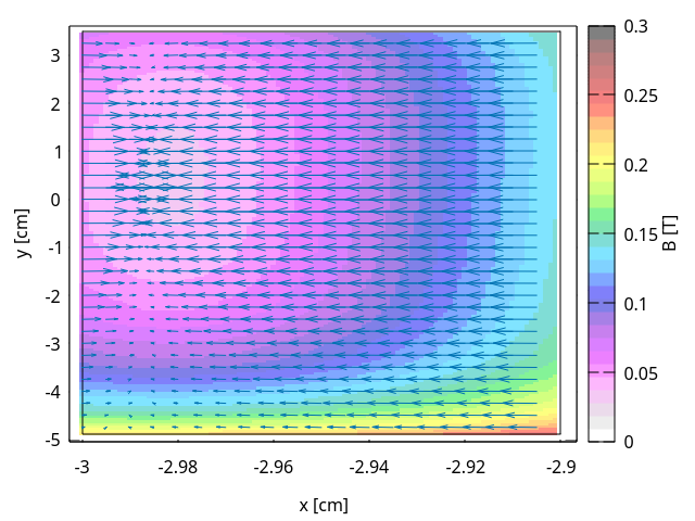
In your specific case, I notice that when y > 3.5 you have less z coordinates. Therefore I generated the magnetic field between y = -4.9 and y = 3.5. That should anyway cover most of your geometry.

To declare the field, I need the following cards:

MGNCREAT         300                                                  TESTDIP
MGNCREAT                                         2        85       201 &
MGNCREAT          -3      -4.9        10      -2.9       3.5        30 &&

Then, to specify the data points, you need several lines:

MGNDATA   -1.902E-01 1.205E-01 2.212E-01-8.664E-02 1.195E-01 9.054E-02TESTDIP
MGNDATA   -1.895E-01 1.085E-01 2.375E-01-8.856E-02 1.081E-01 1.066E-01 &
MGNDATA   -1.889E-01 9.907E-02 2.498E-01-8.955E-02 9.901E-02 1.188E-01 &&

… 17085 lines in total!
Finally, you need to assign this magnetic field to the corresponding region:

MGNFIELD           1                        DIPOLE                    TESTDIP

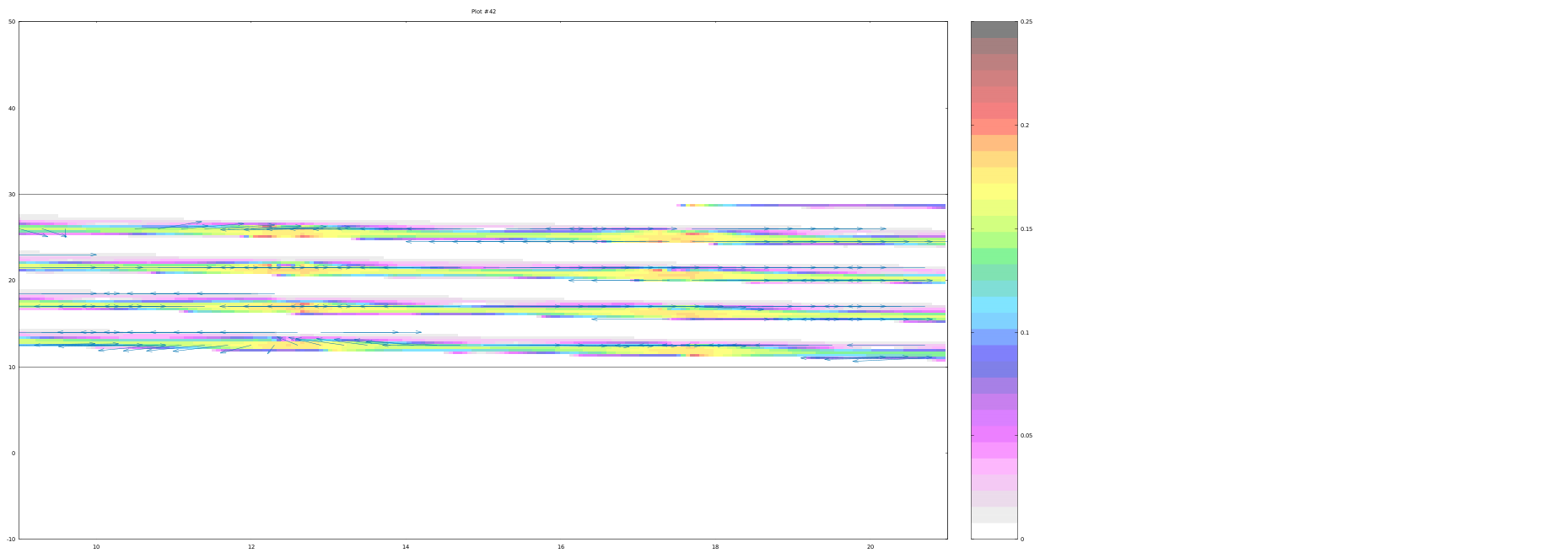
The results are here:
Field map data: testdip.inp (1.2 MB)
Inputfile: test_dipole.inp (1.2 KB)
Field in the xy plane at z = 20:
xy_field

Hi, I really appreciate your response! I have re-structured the data, and have been struggling to get your solution to work. Not sure if I fully understood the way you defined the testdip.inp format. The FLAIR interface has shown to be very unstable and frustrating to work with, it often modifies the parameters of the geometry and materials assigned section after running the script (not sure if this is a known bug?) …

Anyways, below is the input files I have, I have even spacing between the data points so this should not be an issue. I have attached a lower resolution .txt file with the [x,y,z,bx,by,bz] data points (total size is 4.4 MB so had to cut it to below 4 MB to be within upload limits), and the inp. file with the fieldmap data, and also the project files.

dipolefield5.inp (3.1 MB)
ProjectFile.inp (7.0 KB)
dipolefield5.txt (3.5 MB)

It appears that the data is being read incorrectly based on the .err file

  *** The 1th field  -0.2 -0.1 of the following input card ***
 MGNDATA    -0.2 -0.10.1 -0.0 0.2 -0.0TES      TDIP                              
  *** does not contain a valid formatted fortran real number    ***
  *** when one is expected ***

Do you know where the issue may be? Note that in the .inp file the “TESTDIP” is not written as “TES TDIP”. Not sure why it reads it as such?

Thanks again I really appreciate your help with this!

Hi Arpad,

the implementation of the magnetic field card is incorrect. There are two problems:

  1. The first MGNDATA line does not contain the “TESTDIP” string in the sdum, but “&&”, which indicates a continuation line (and the second line should have “&” instead of “&&” as well).
  2. You are not respecting the FIXED structure of the inputfile, which in FORTRAN language is: (A8,2X,6E10.0,A8). Therefore you have 2 possible choices: either you respect it, or you switch to FREE format (7.22.29. FREE — FLUKA Manual). I attach here a possible example with the FREE format.

dipolefield5.inp (3.7 MB)

Just a side comment, the FLAIR interface is not thought to be used to manually modify large set of mangetic field data, which are normally produced by ad hoc scripts.
Let me know if you have any additional doubts.

Cheers,
Daniele

Hi Daniele,

I have managed to import the magnetic fields into FLUKA, however, I am quite certain that they are not interpolated and they are also not defined correctly.

Can you clarify exactly how the input file with the magnetic field data is created? I.e. how the list of XYZ coordinates with Bx, By, and Bz can be converted so that the fields are read correctly by FLUKA?

Thanks again,
Arpad

Hi Arpad,

the field looks indeed off.
I will try to clarify how you should provide your data to FLUKA. As stated in: 7.22.48. MGNDATA — FLUKA Manual, the user should input the values of the field in the interpolation grid described via the MGNCREATe card.

Considering now a 2D slice of a generic 3D grid:

y
^
|
9-----10------11------12
|      |       |       |
5------6-------7-------8
|      |       |       |
1------2-------3-------4---> x

You should fill the WHATs of the MGNDATA card with the magnetic field components. This means that you should add for each point Bx, By, Bz.

A concrete example would then be

MGNDATA   Bx(1) By(1) Bz(1) Bx(2) By(2) Bz(2) TESTDIP
MGNDATA   Bx(3) By(3) Bz(3) Bx(4) By(4) Bz(4) &
MGNDATA   Bx(5) By(5) Bz(5) Bx(6) By(6) Bz(6) &&
...

And so on, until you fill all your points. You should do this for all your slices, incrementing each time the z coordinate.

As a personal suggestion, it could be useful if you are able to plot your field independently from FLUKA, just to have a double check of the validity of your field.

Cheers,
Daniele