Hello again, I have another question regarding the mesh import to flair:
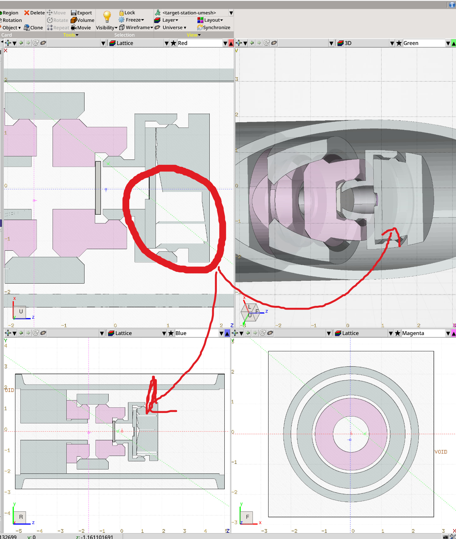
I import a CAD drawing via the UMESH card, using the new FLUKA_mesh_fix.py to convert and fix the geometry. The resulting geometry looks good in the 3D view, but the 2D views show some weirdness (artefacts) and I was wondering how to fix this or if this is even a problem. If I zoom in enough on the 2D view the artefacts vanish. I also checked the geometry with gmsh GUI and also there the geometry seems fine.
It’s not really an issue, simply a way how Flair renders tetrahedrals bisect by section plane in viewport, sometimes because of limitation in numerical precision.
Actual artifacts will look like presence of tetrahedrals of material A inside region where material B is assigned.
If you don’t mind, I have another similar question:
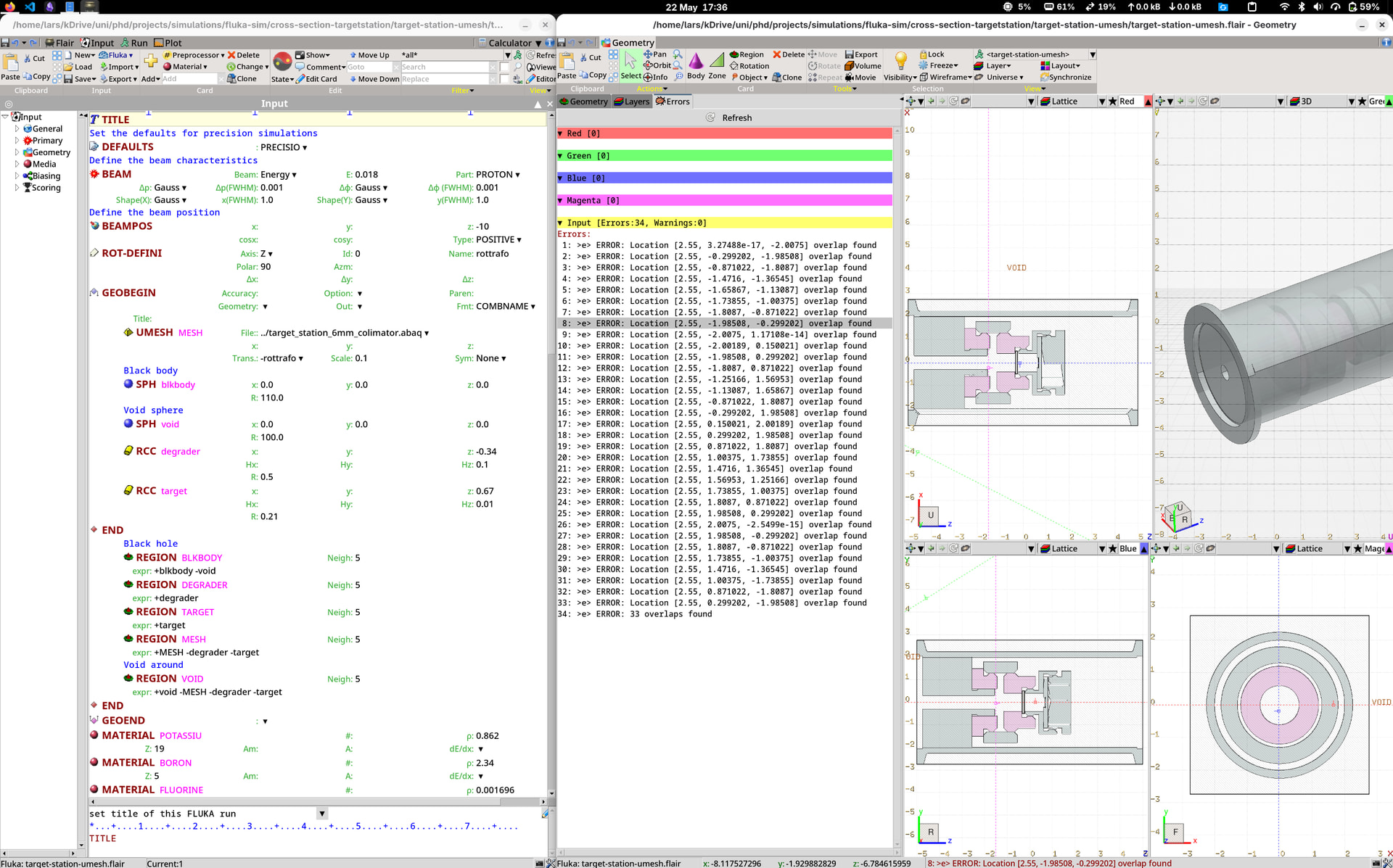
I have a lot of overlap ERROR in my geom-viever, I assume it is due to the conversion from .stp to the .abaq file that I get some overlap between the individual parts. However when I run the simulation I get no errors. Is this something I can fix, maybe try other arguments for the conversion script?
Yes, it might happen due to meshing closely located parts. Common tolerance value for overlaps in CAD and meshing tools is ~1e-6 since in reality it’s really hard to manufacture parts with precision < 1 um. Instead, a tolerance requested by FLUKA is ~1e-8–1e-10.
There is an option in the script that may fix overlaps, but I deliberately disabled it since Gmsh algorithm was not very robust for complex geometries.
You would need to use a different meshing tool (Ansys/Cubit) to create a so called shared topology to generate conformal mesh.. But this will require much more time and fine-tuning meshing options in these programs.
These issues are usually tolerated by FLUKA, and introduce quite small uncertainty, few orders less than 1% (depends on mesh resolution).