Issue with Bremsstrahlung Generation and Energy Deposition in FLUKA Compared to Geant4

Dear Expert,

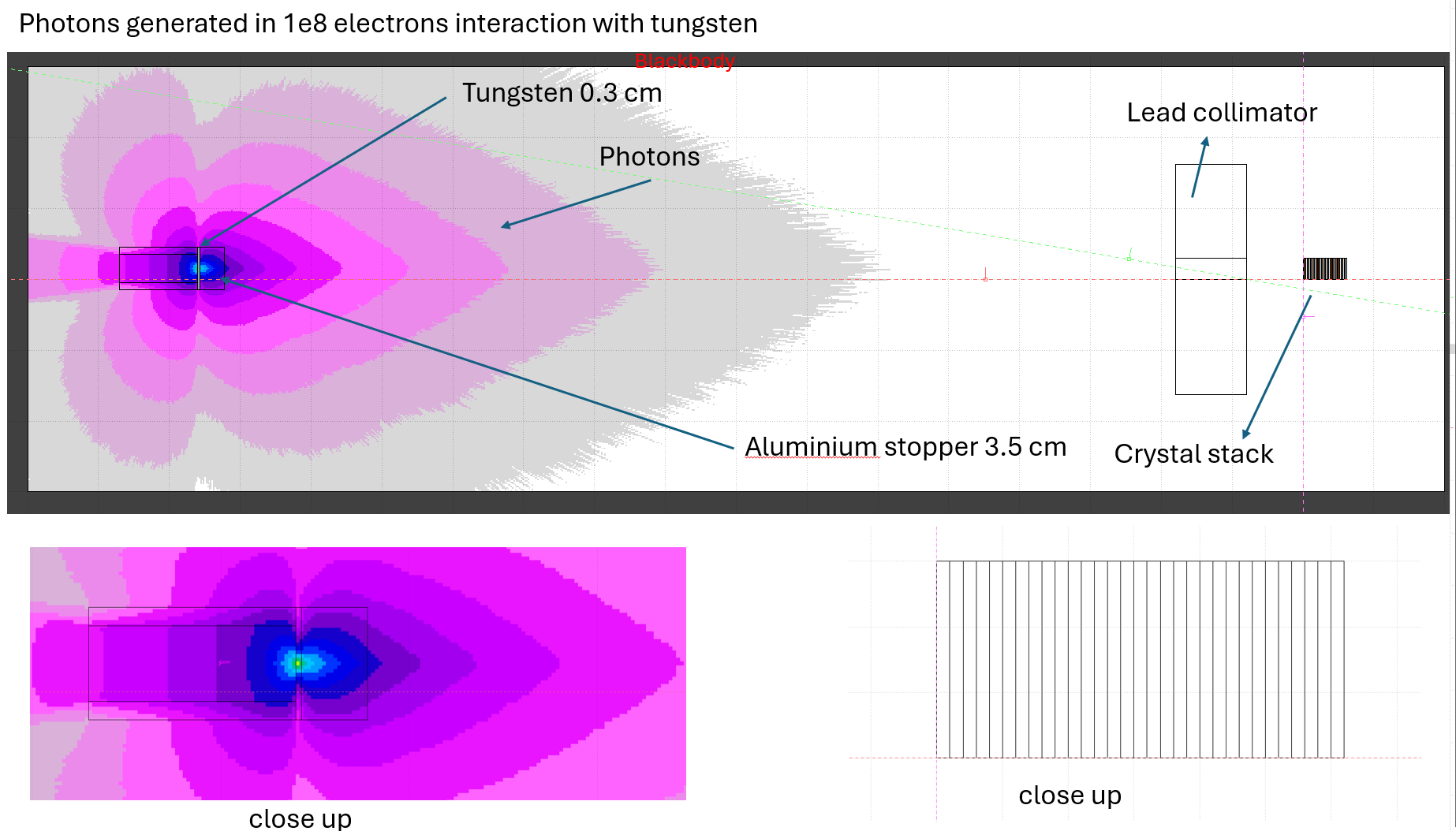
We are performing a simulation to study energy deposition inside a scintillator stack. The photons of interest are produced by the interaction of an electron beam with a tungsten target, with a 3.5 cm thick aluminum stopper placed after the target to stop electrons. Our aim is to observe the photon-induced energy deposition (E_dep) in each crystal of the stack.

Here’s a summary of the two cases we simulated:

1. Photon Beam (Benchmark Test)
First, we simulated a monoenergetic photon beam of 500 keV (no tungsten, only the aluminum stopper) in FLUKA. We scored the region-wise E_dep in each scintillator crystal using the USRBIN card. The same setup was also implemented in Geant4. The results from both simulations were in good agreement in terms of energy deposition values.


2. Bremsstrahlung Photon Generation
Next, we attempted to simulate bremsstrahlung production:

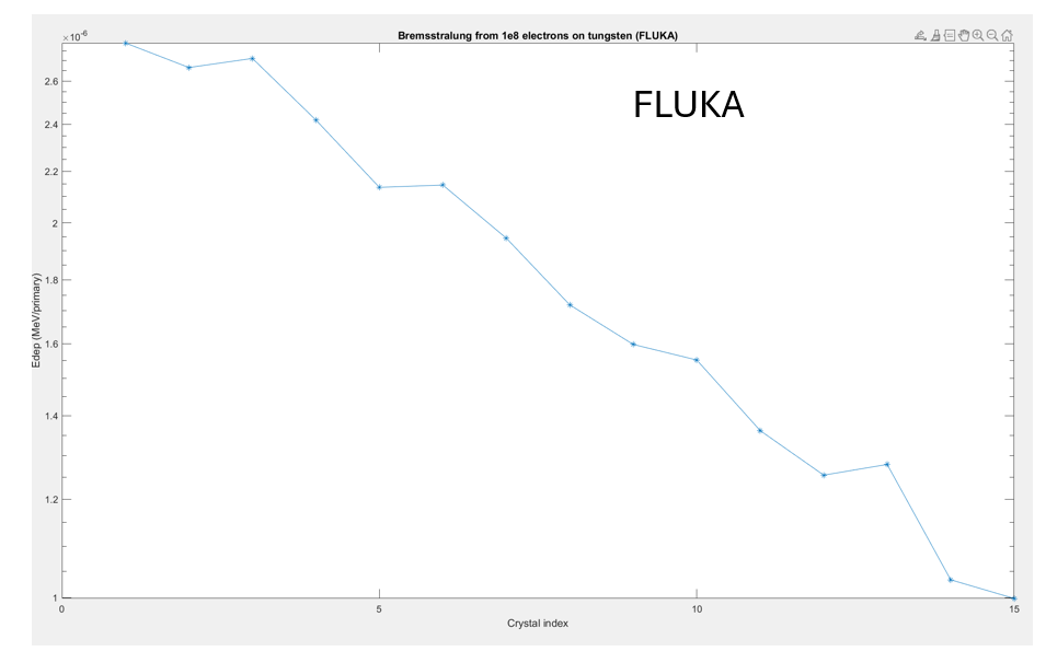
  • In FLUKA, we added a 3 mm thick tungsten target before the aluminum stopper and sent 1e8 electrons onto the target.
  • We scored the energy deposition in the crystals using a USRBIN (region-wise) card.
  • Additionally, we included two more USRBIN cards to monitor photon and electron fluence separately.

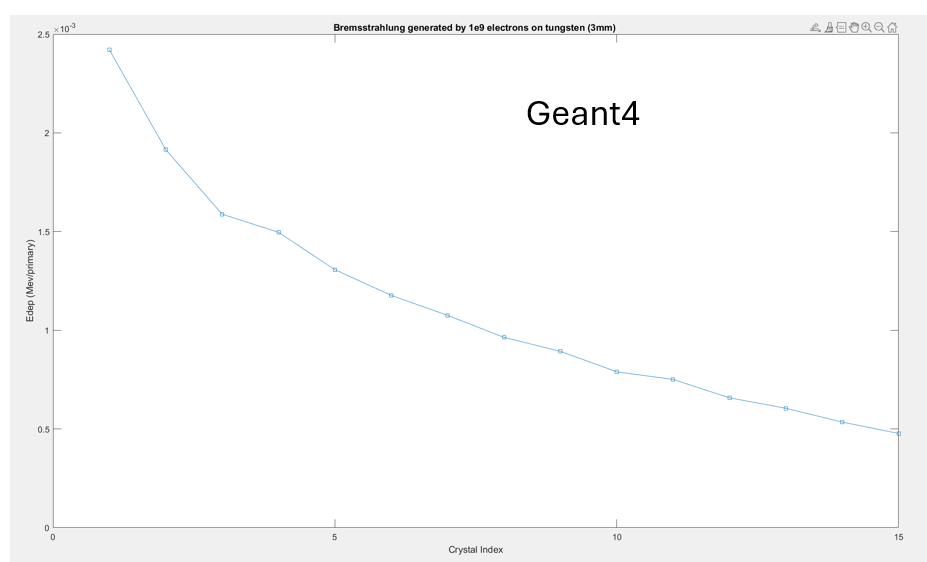
However, the results showed almost no particles reaching the crystals and very low or negligible energy deposition, unlike in the Geant4 simulation (run with 1e9 electrons), where we observed reasonable E_dep from bremsstrahlung photons.

Due to FLUKA estimating around 7 days for 1e9 electrons, I chose to simulate with 1e8 electrons, which took aroung 2 days. Still, the large discrepancy (around 3 orders of magnitude) in E_dep compared to Geant4 is puzzling.


My question is:
Is there something I might be missing in FLUKA with respect to the correct setup or physics processes for bremsstrahlung photon generation and transport? Are any additional cards or settings required to ensure proper bremsstrahlung simulation?

3. In this simulation, I also reduced the size of the blackbody and void volumes into a smaller rectangular slab shape.
Could such a modification affect the photon transport or simulation behavior in FLUKA? I am particularly wondering if this could limit bremsstrahlung photon propagation into the scintillator region or unintentionally absorb/interfere with them.

Thank you in advance for your guidance.
cali_new_setup_temp.inp (7.1 KB)
cali_new_setup_temp.flair (6.5 KB)

Best regards,
Shubham Agarwal

Dear Shubham,

Thank you for your clearly formulated question.

The reaction in which you are simulating is one that is statistically challenging.

As such I would recommend the following to reduce the computation time on aspects that are not of interest:

  1. Cut the geometry with a blackhole immediately after the source in z - to save time tracking particles traveling backwards. (I.e. move the zmin to be ~ 161cm)

  2. Either cut the X or Y coordinates of the void body to be closer to reduce the lateral part of the simulation for particles that will pass to far to contribute to the measurement. Or introduce a cone body to achieve the same effect.

  3. Following both 1. and 2. should speed up the simulation, but if it is not sufficient - you can also consider adding importance biasing in the air region between the source and the collimator. I have provided a link to the FLUKA beginners course (both the lecture slides explaining how to implement this, and also a worked example which is very similar to your application.)

  1. If this is still not sufficient then you could try the more extreme approach of setting the collimator to be a black hole. This would only be applicable if you didn’t expect much contribution from secondaries.

I hope this helps. Please let me know if these suggestions are not sufficient.

Many thanks,

Katie

Dear Kate @kltaylor ,

Thank you for your detailed answers, and apologies for my late reply, I was on vacation.

As you suggested, I implemented points 1 and 2: cutting the geometry after the source with a blackhole, reducing the X and Y coordinates as well as the void and blackhole regions, and also reducing the size of the collimator lead block to minimize the void size. However, I still do not see much difference. I checked this with 1e7 electrons with 1 cycle run.

Next, I tried to understand and apply biasing from the examples. Since in my case the void is air, I implemented a rectangular biasing region between the aluminium stopper and the collimator, as you suggested for the air region between the source and collimator. I tested two configurations:

  1. From region: airgap → to region: airgap

  2. From region: aluminium stopper → to region: airgap

In both cases, I set the importance to 2. Now I do observe some photons reaching the collimator and the stack. However, in the region-wise energy deposition file, the values remain approximately the same, though with quite high statistical errors (possibly because of running only 1 cycle). For these runs I also turned off the prod-cut and transport in EMFCUT.

Regarding point 4, I am still unclear: if I set the collimator as blackhole, how will particles reach the stack?

So, I wanted to ask whether I should try a more aggressive biasing approach, starting from the airgap to the collimator, then to each individual crystal and the airgaps between them.

Or, is there another approach you would recommend?

cali_new_setup_temp.inp (7.7 KB)

cali_new_setup_temp.flair (7.0 KB)

Kind regards

Shubham Agarwal

Dear @talktoshubhama ,

Firstly to answer your question around point 4 - in this part I had meant only to set the lead part to void (as particles impacting her are unlikely to propagate further and their interaction would take up CPU time.) Although as you have pointed out, in the absence of many particles reaching here it is perhaps less effective.

Regarding the reduction in the geometry - it appears you have an error around your source regions (your iron cylinder) - as the new void RPP is intersecting.

The importance biasing is most effectively implemented when applied to adjacent regions. For instance, segmenting the void region between the source and the target into separate regions (including the air region of the collimator), and use the surface splitting feature (as you have) but extending this for each adjacent region with increasing importance (similar to the example in the course - slides 8-14). This should enable to particles to propagate more effectively.

Hopefully the implementation of this should assist in improving your statistics - please let me know if it does not, or if my explanation was unclear.

Many thanks,

Katie

Additionally the target region should also remain at an increased important to the region prior to it. In this case as you have many regions - so I would suggest either setting them with increasing importance, or the same importance. Its a little fiddly unfortunately.

Dear Kate @kltaylor ,

Thank you for this solution. I’ll try this approach and experiment with what importance values work best. I have an additional question: if this method works and produces proper results, will the energy deposition in the region-wise USRBIN reflect the exact values, or will I need to adjust/transform them further because of the biasing and different importance settings?

Regards

Shubham Agarwal

Dear Shubham,

I hope it works well for you.

The results will be weighted accordingly. However, the USRBIN will take into account the biasing and normalise for this automatically, and so you will not have to do anything when using USRBIN to score.

Hope that helps.

Many thanks,

Katie

1 Like