LATTICE card, role of SDUM

Dear colleagues,
I write you for a clarification concerning the LATTICE card.

I wrote the very simple example attached here (test.inp)
test.inp (709 Bytes)

In this, I define a “basic cell” for the geometry (the region B1, that contains an internal structure), and two “blank” regions for the replica (B2 and B3). Then, I define the lattice and a transformation to transform from the replica volume to the basic cell

LATTICE B2 B3 101 102 transl
ROT-DEFI 100 -40 transl

If I understood correctly, this means that the B2 and B3 are replicated regions and the corresponding lattice numbers will be from 101 to 102. The transformation from the regions to the base cell is a translation along -X of 40 cm. The result from FLAIR is the following:

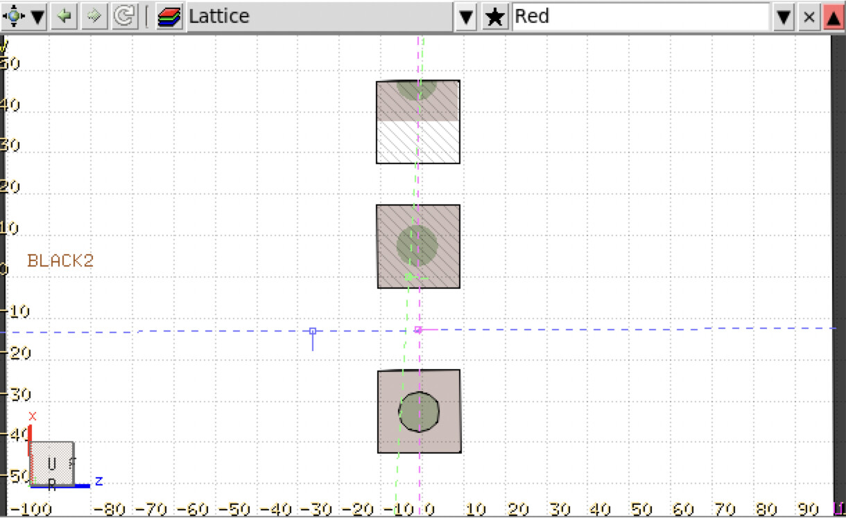
I was quite surprised to see that both container regions are filled with the replica, i.e. I think I have not fully understood the role of SDUM in LATTICE.

  • If the transformation is from the container region to the basic region, it would be reasonable that each replica has its own transformation. However, if this is the case, what is the role of WHAT(1) and WHAT(2)?
  • Why can more than two (different) container regions be specified here, if the same transformation is to be used?
  • Or maybe there is a way to have a “parametric” ROT-DEFI version, so that the first container region is translated to the basic cell, the second container regions is translated to the first container region, …

For this example, I would thus expect this code to be the correct one:

LATTICE B2 B2 101 101 transl1
ROT-DEFI 100 -40 transl1
LATTICE B3 B3 102 102 transl2
ROT-DEFI 100 -80 transl2

Thanks,
Bests,
Andrea

Dear Andrea,
your expectations were substantially correct and your surprise is justified. When moving beyond the geometry visualization in Flair (that in this ill-defined case does not coincide with the actual interpretation by FLUKA) and trying to run FLUKA, your input would crash, for two reasons.
One - fundamental - reason is indeed that your example requires two different transformations, as you code them in the end, since the replica region B3 (contained in the body BOX3, which by the way was meant to be defined along x from 50 to 70 cm and not from 40 to 60 cm) must be mapped onto the prototype contained in BOX1 and cannot be mapped onto another replica instead.
The second - formal - reason is related to the peculiarity (admittedly questionable) of the LATTICE card syntax, where you are not allowed to mix names (for regions) and numbers (for lattices). This means that you should rather input:

LATTICE           B2                        FIRSTL                    transl1
LATTICE           B3                       SECONDL                    transl2

where FIRSTL and SECONDL are arbitrary lattice names, internally corresponding to lattice numbers 1 and 2 (regular regions carry the lattice number 0).
Coming finally to the alternative use of the LATTICE card you were wondering about, this is left for (more exotic) configurations, where a sequence of replica regions can be associated to the sequence of respective prototypes by the same transformation, as you pointed out. In this case, a single LATTICE card should feature the latter in the SDUM, as well as the region sequence by numbers (!) and the associated lattice number sequence.
Ciao
Francesco

Dear Francesco, thanks. This makes perfect sense, and now I understand what is the role of WHAT(2) and WHAT(3) in LATTICE card; I think for example of a LATTICE where the base cell is made of two or more non-contiguous regions.

Bests,
Andrea