Dear Yu,
I apologize for the late reply.
You mentioned the nuclear reaction energy cutoff in FLUKA is 1.1 MeV/n, which means I cannot perform the calculation I want. So why does FLUKA need to set this cutoff, since nuclear reactions can actually occur below this energy value, is this related to the cross sections?
The 1.1 MeV/n cutoff serves as a general rule of thumb to roughly account for the fact that there is a Coulomb barrier energy below which nuclear reactions are not accessible. Unavoidably, for some situations (like in your specific case) this general recipe may have to be adapted.
By the way, where do the total and differential cross section data for the D(3He,p)4He nuclear reaction come from?
The reaction cross section comes from a parametrized expression fitted to experimental data.
The differential cross section, instead, is not parametrized. At your energies, for deuteron on 3He (above 1.1 MeV/n!) a compound nucleus is formed, which then passes through FLUKA’s Fermi break-up model to sample the possible final states.
Also, assuming I use some other Monte Carlo software, such as Geant4 or some you may know of, can they perform the related calculations?
You may need to address the question in the corresponding forum.
Assuming I do not choose S treatment for deuterium, does FLUKA have a default value for this, since our material is actually deuterium gas, is the related treatment still needed?
FLUKA does not activate S(α,β,T) thermal scattering laws by default, except for H bound in water (for which S(α,β,T) is activated automatically). Moreover, since there is no S(α,β,T) for D in the environment of your target (ErD2) in the databases, there is unfortunately nothing you may request. De facto, thermal neutron scattering will be on unbound D.
Instead, if your material is really D2 then you may request S(α,β,T) for 2H bound in D2_ortho and D2_para environments (see our previous discussion).
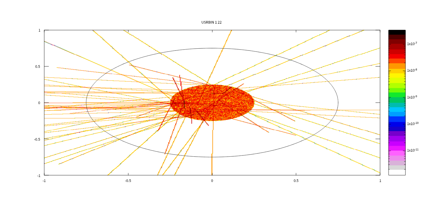
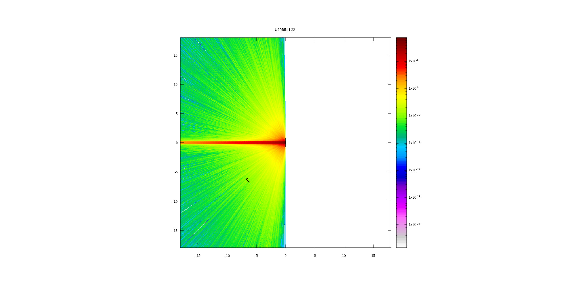
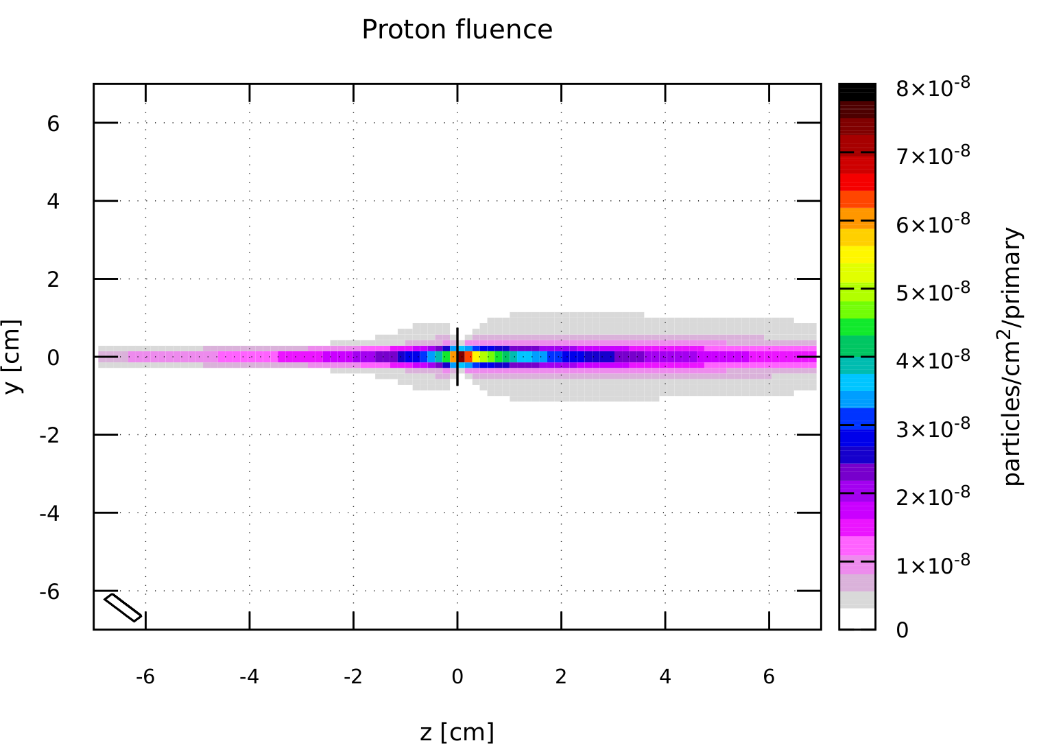
In the spatial distribution of nuclear reaction protons, there is a red line along the transverse direction. This line is actually the incident direction of the 3He beam, does this mean some protons are generated during the 3He beam transport?
Protons are generated from the D(3He,p)4He process.
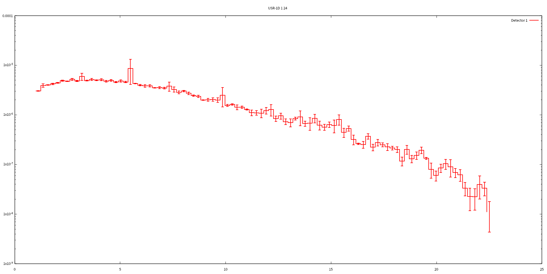
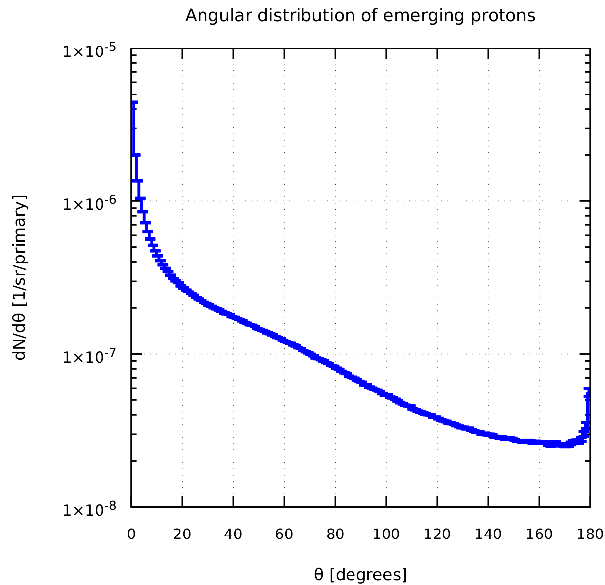
In the plot attached below is the angular distribution of protons emitted from the interaction of the 3He beam with the ErD2 target:
As you can see, most of the protons are emitted in the forward direction, while there is also a small, but noticeable increase in the large emission angles (close to 180 degrees). The protons emitted at small angles are, however, entering the Molybdenum target, where they interact and exhaust their energy.
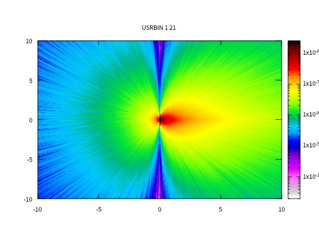
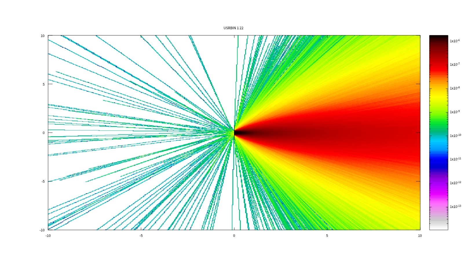
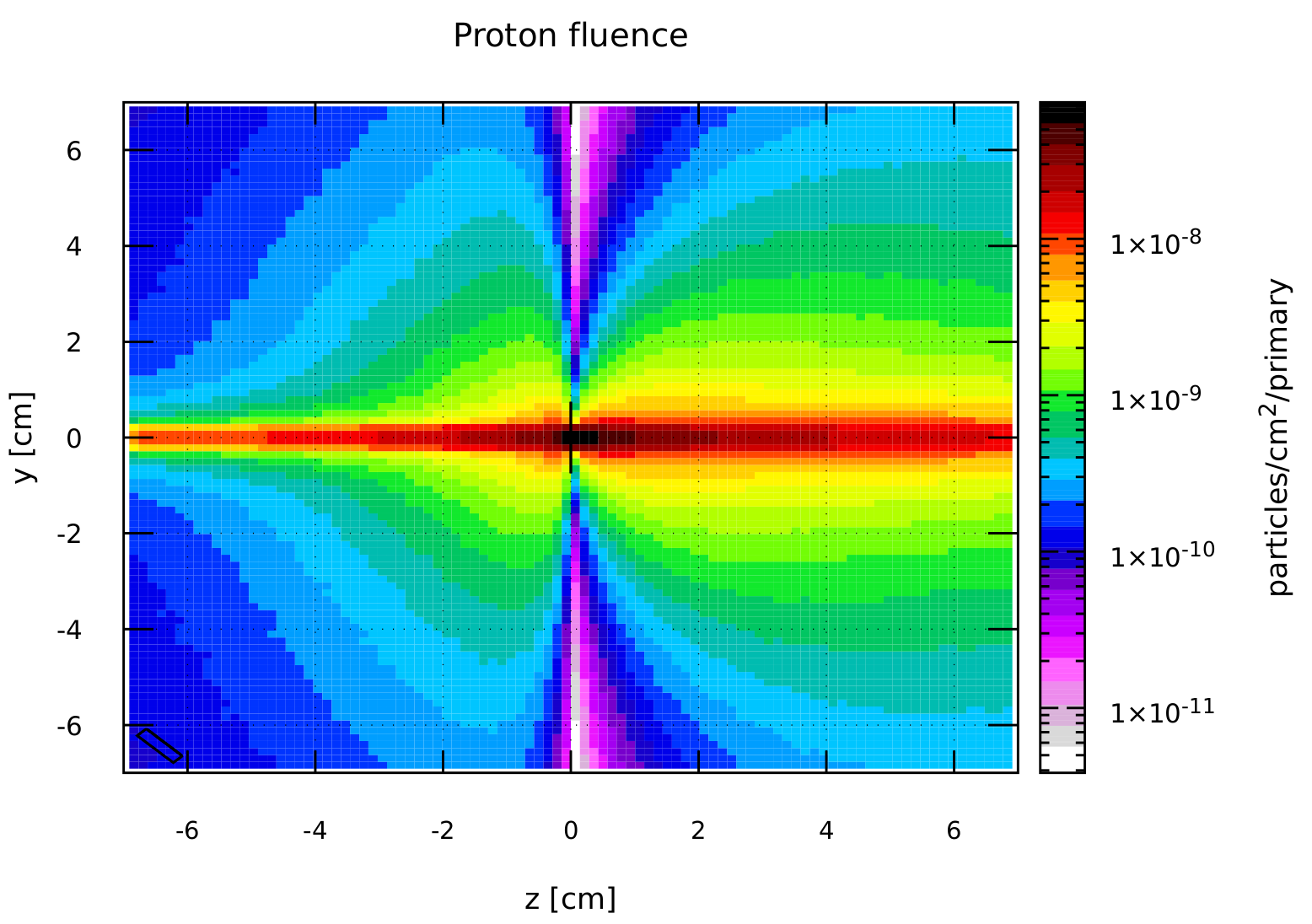
Removing the Molybdenum target and plotting the 2D fluence of protons you can observe clearly the effect described above: most protons are forward peaked, but there are also some protons emitted in the backward region, which were the ones you observed:
Setting the colorbox in linear scale, it is even more evident that there are less backscattered protons compared to the ones emitted in the forward direction:
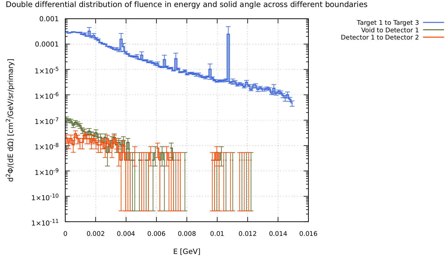
I got no results when scoring DETEC1 to DETEC2 using USRBDX. I don’t know what went wrong.
There are two reasons why no results were obtained:
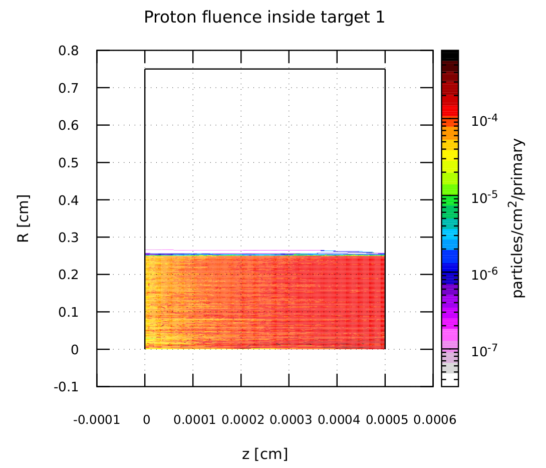
- There is a geometric effect due to the position and size of the detectors, which happen to cover a very narrow solid angle and in this way managing to capture only a limited number of particles. In the plot below you can see that from the proton fluence from Target 1 to Target 3 (in blue) only a very small amount of it arrives at Detector 1 (in dark green) where some of the protons interact in Aluminum and are stopped there, resulting in even less protons arriving at Detector 2 (in red).
- There is also a problem of low statistics. Given the aforementioned geometric argument, you will need to simulate a sufficiently large number of primary particles in order to generate enough protons which can make it to Detector 2.
Also, for actual detector operation, is current more meaningful than flux?
Possibly you mean current vs. fluence (time integral of the flux, readily accessible a la Monte Carlo).
If your detector is sensitive to the number of particles passing through it, you would need the current. Instead, if your detector is sensitive to the density of track lengths (e.g. if it measures energy deposition and related quantities), you would need to assess the particle fluence.
I wanted to try to get something like the output energy spectrum from a detector (Gaussian peak), so I chose to use DETECT, but it seems there are no results. I don’t know what errors occurred.
The lack of results comes from the two points detailed above: the geometric effect of the small solid angle covered by the detectors due to their position and size and relatively low statistics. Once you have enough statistics, you can proceed with the Gaussian broadening. However, be aware that event-by-event analyses are not recommended when using biasing techniques. See Note 2 in: 7.22.14. DETECT — FLUKA Manual.
Cheers,
Alexandra