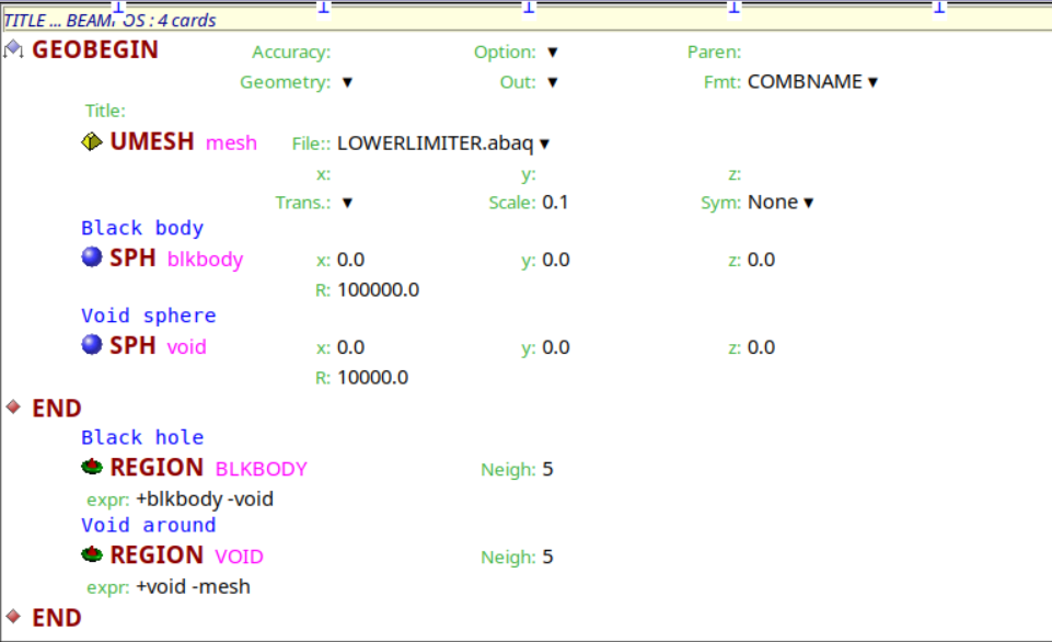
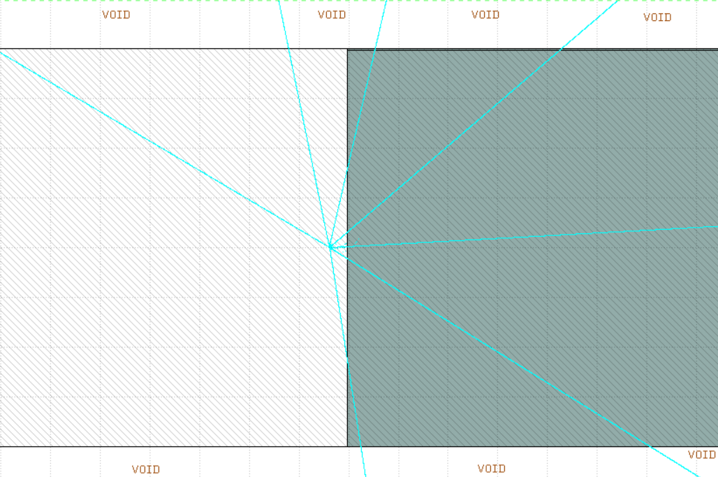
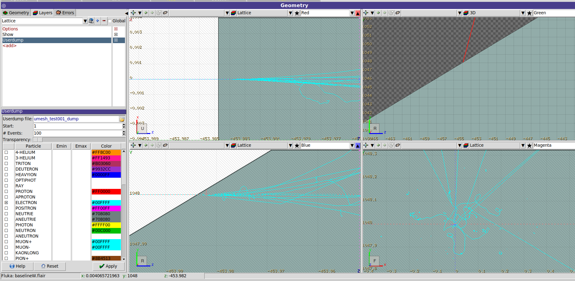
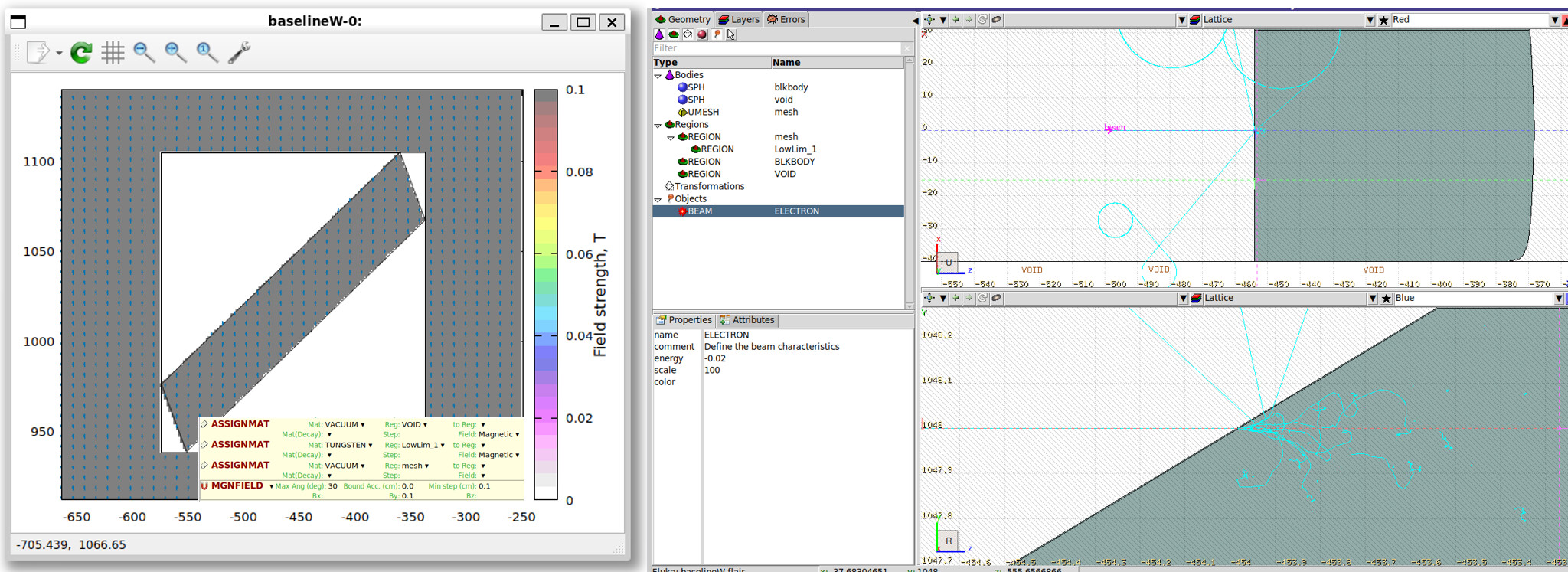
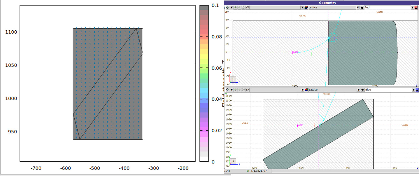
I am using the UMESH card to import my CAD model from an abaq file. It seems that Flair imports the geometry correctly, although I can only visualize it in one of the Geometry view panels.
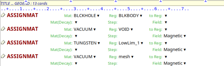
However, I am not convinced that the regions are being handled correctly. In particular, I would like to assign the void material to the bounding box and tungsten to the imported CAD geometry, but I am not sure whether the regions are being created or interpreted as expected.
I say this because, when I simulate the interaction of an electron beam with the geometry, it appears that collision processes start already within the bounding box, whereas I would expect the electrons to experience only the magnetic field there, with no material interactions until they reach the tungsten geometry.
I have one last question regarding the scoring procedure. I would like to score the deposited energy, and I tried using the USRBIN card with the type set to UMesh. Is this the correct approach?
I’m asking because, in the Plot section, I receive a warning stating that a 2D projection cannot be generated.
In general, the UMesh type scoring is useful if you want to use it as a further data input for the FEM simulations. It is stored as 1D array (value per tetrahedral/hexahedral element), hence it’s not possible to create a 2D projection on a Cartesian grid. But you can overlap it in Geometry tab for the visual inspection or plot 1D plots in Plot tab.
For 2D projections, you could score using common XYZ or RPhiZ types of USRBIN, and applying weight correction to the scored values in the boundary bins via comscw.f