Dear Fluka community,
I plan to calculate the energy deposition on graphite of 8GeV electrons. The annular source is used in the calculation. There were some problems in the calculation.
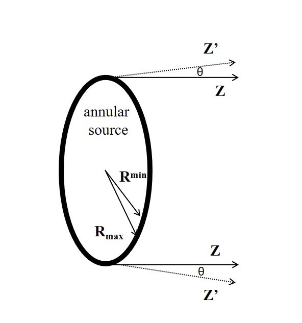
1 The electron direction of the annular source is shown in the picture. The angle between the exit direction Z’ of the electron and Z is 30°. So, the source_newgen.f file was used. However, the output was not what I wanted. Please help me to check the source_newgen.f file.
Your problem is non-trivial, but it’s rather a geometry related issue than something specific to FLUKA.
Starting from your last question: Yes, you can have your own source_newgen.f routine linked with the dpmqmd library. The easiest way to do it is to use the Compile bookmark in Flair and choose ldpmqmd instead of lfluka in the window just next to the Clean button.
You can find more details about how to compile your own source routine in the materials from the FLUKA Beginner’s course
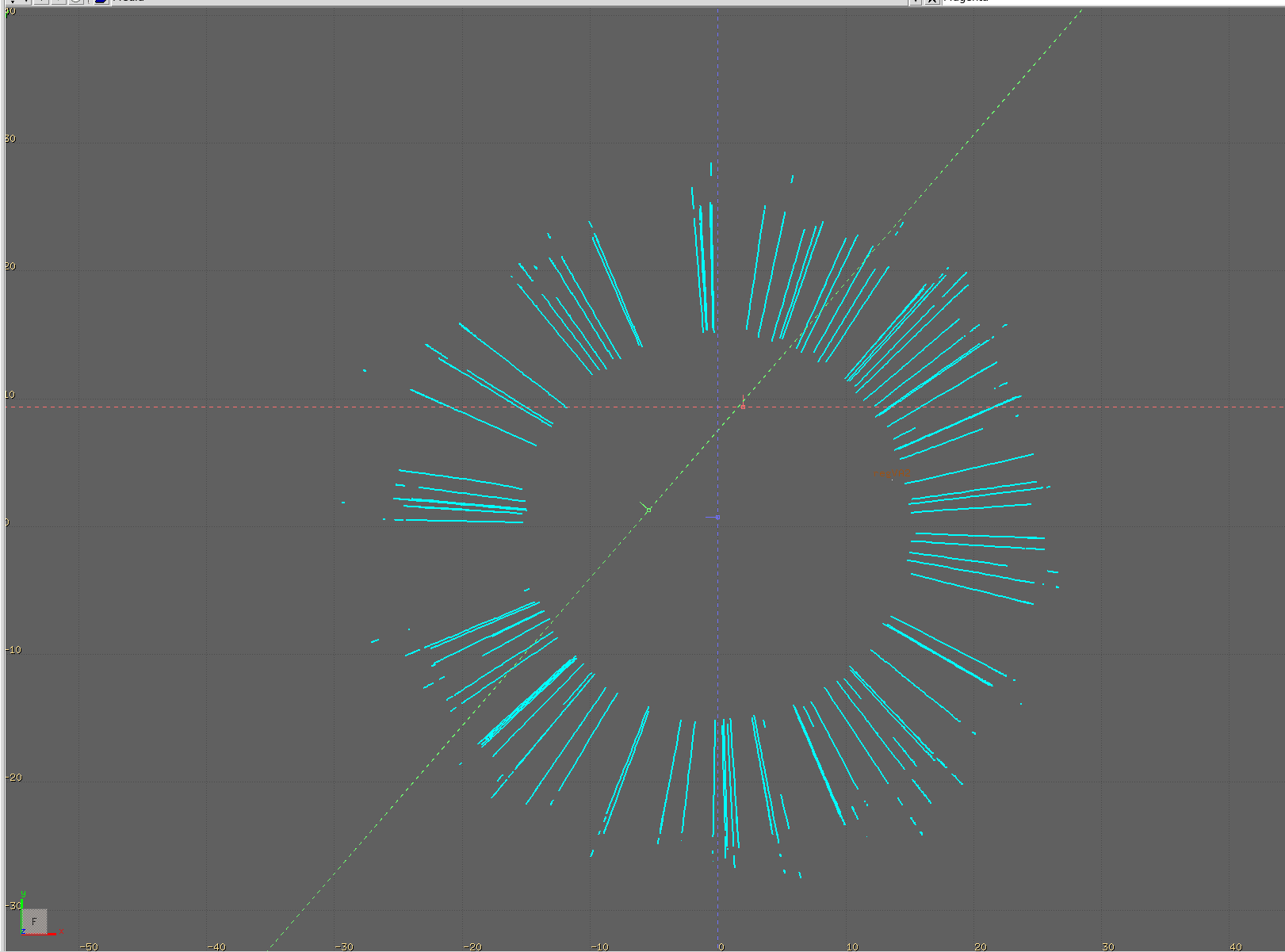
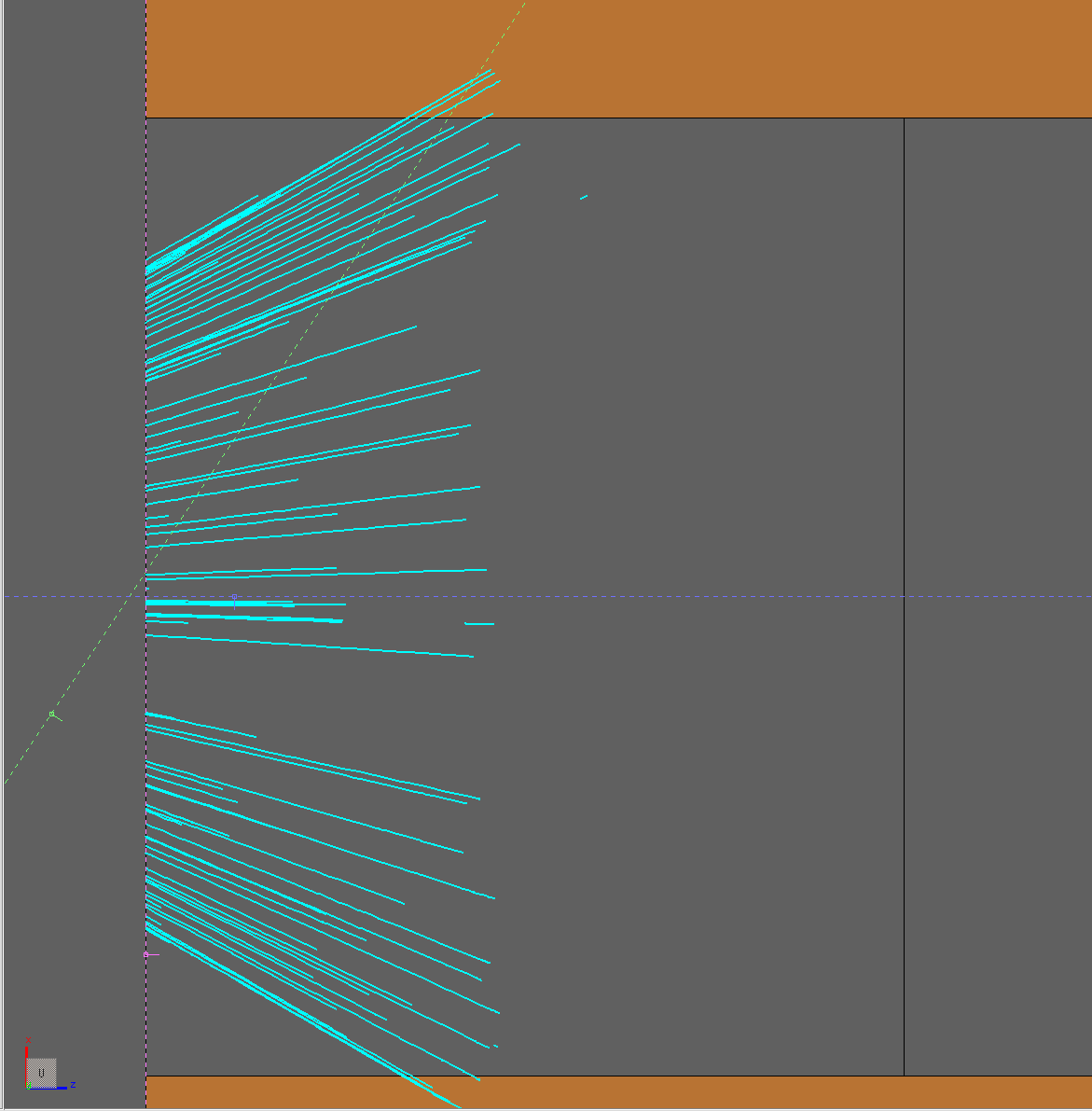
Coming back to your source problem. Please find below two screenshots that I took while trying to find a solution. Is this what you expected?
It’s true that you need to use a custom source routine and your approach looks like a good start. The way I approached this problem was first to find a vector which is perpendicular to both the R vector and the Z-axis. You can get it with a cross product. Let’s call this new vector U. Then, noticing that R and Z are perpendicular, I found a rotation matrix around the U vector to rotate the initial R radius by 60 degrees towards the direction of Z (pay attention to the rotation sign!). The angle between the rotated R and the Z is now 30 degrees and the orientation of your direction points to the outside of the source circle.
I am sure you can figure this out!
In case you won’t manage to find a solution, let me know.
Thank you for your reply.
Yes, this picture shows the emit direction of electron what is I wanted.
I can understand your approach. However, I do not know how to create the new vector U and rotate R.
Are there any relevant example which I can learn from?
First to get the U vector you can use the cross product:
between the R vector and the Z-axis. Your R vector coordinates are non-zero only in X and Y and they are equal to coordinate_x and coordinate_y from the source_newgen.f routine after you call the sample_annular_distribution function. The Z-axis is of course just (0,0,1).
The cross product is non-commutative so to get the right rotation direction be careful which vector you place first in the operation.
Once you have the U vector as your rotation axis, you can use the Rodrigues’ formula:
to rotate R around U by 60 degrees. Then you get the rotated R, let’s call it R’. The magnitude of R’ is the same as R and equal to sqrt(x^2 + y^2) where the x and y are the original coordinates of R.
In the very last step, you need to find the directional cosines and to do that you can simply take
cos_x = R’_x / |R’| = R’_x / sqrt(x^2 + y^2)
cos_y = R’_y / |R’| = R’_y / sqrt(x^2 + y^2)
cos_z = R’_z / |R’| = R’_z / sqrt(x^2 + y^2)
I hope that helps!
It’s possible that there is a simpler way to solve this. The one that I used takes a very general approach, but, as I wrote before, I don’t think it is a trivial problem.