Currently, I am using the Umesh card, and after meshing with the geom_mesh tool and uploading the mesh file, I am still encountering a box holder (container) around the geometry of interest, is visible in the geoview.
Could you please advise on how to remove it? so I can have at the end the meshed geometry only.
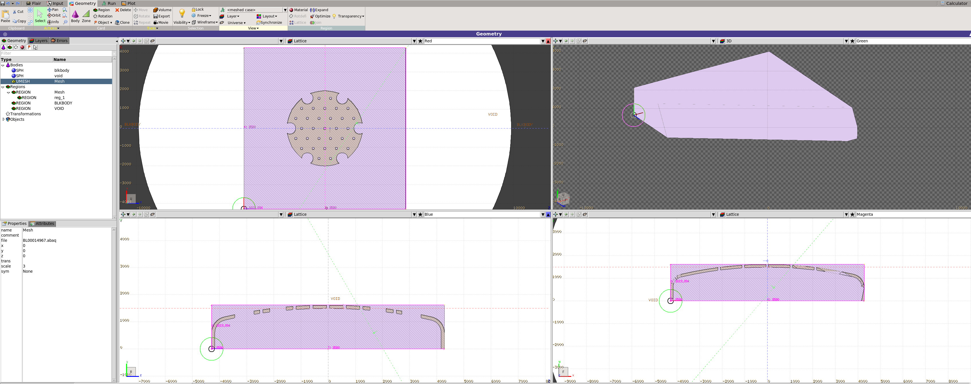
This is a correct behaviour, your mesh geometry will be inside the bounding box with vacuum inside (lattice-like). It’s needed for a smooth transfer between FLUKA CSG tracking logic and 3D mesh tracking.
Could the bounded box be removed to allow for better visualization of the geometry?
If it is filled with a material other than vacuum by default, should I revert it back to vacuum?
How can the scoring be performed in a vacuum, considering that some quantities, such as ambient dose, do not have a meaningful representation in a vacuum?
It will be displayed clearly in a 3D viewport, where gases become transparent (and other materials if their default appearance was edited). But it will be easier to change the Mesh region transparency:
In other viewports, the bounding box with vacuum will be shown in a diagonal hatch pattern.
.
Custom material can be displayed in the same way if you change color of material to be white.
All sorts of materials can be assigned to the void volume inside the bounding box, but as was pointed out, it will affect visualization in cross-sectional viewports.
Following up on the same topic, if possible, and if another thread should be opened as well let me know please so I do it.
These kinds of errors are not fixed by the mesh tool itself, which means only the geometry file needs to be cleaned or modified, and the tool is not producing at the end any meshed file.
Am I correct in my understanding of the mesh tool, based on the website and yesterday’s webinar?
Ambient dose (DOSE-EQ) can be meaningfully calculated in vacuum, since it results from fluence folding with conversion coefficients. Quantities that cannot be scored in vacuum are deposited energy (ENERGY), absorbed dose (DOSE), DPA, and residual nuclei.
Yes, it’s the same tool demonstrated in yesterday’s webinar.
As a first step, I recommend trying to mesh with the --stl flag enabled; this may improve the quality of the surface mesh. If that doesn’t resolve the issue, consider exporting and meshing the CAD model in a different file format.
Edit: Also try to decrease --voxels number for remeshing (20-40 instead 60) , it helps in some cases.
If the problem persists, you’ll need to identify the region where the overlap occurs and simplify the geometry in that area.