I am currently working on calculating neutron energy spectra generated by 215 MeV protons impinging on a tissue-equivalent target. Specifically, I am interested in spectra corresponding to backward angular bins, ranging from 90–105° and 165–180°.To achieve this, I am using inverse cosine-weighted boundary crossing estimators (USRBDX), which compute the neutron fluence across a surface. The solid angle for each bin is determined using the relation: ω(θ)=2π(1−cosθ) .However, while setting up the input file, I encountered an issue: a red entry is appearing, indicating an error in the input.
I would appreciate your guidance on how to resolve this issue. In particular:
• Could the problem be related to the way the angular ranges or cosine-weighting is implemented?
• Is there an example or best practice for defining these estimators for backward directions? ex_bkag.inp (2.2 KB)
I had a look into your input file and I immediately noticed that you are exceeding the solid angle range allowed in your USRBDX card. When you are using a one-way scoring (as it is the case in your input), the possible solid angle spans from 0 to 2pi, because you are scoring the particles crossing the region boundary (a plane) in one direction only (for example leaving region 1 and entering region 2 but not leaving region 2 and entering region 1) therefore only half of the solid angle sphere is covered by the scoring.
In your case, you have a TARGET box completely surrounded by a VOID region, so I understand why you would think that a full solid angle should be covered in the scoring, but quoting the FLUKA manual:
Angular distributions must be intended as distributions in solid angle 2pi (1-cos(theta), where theta is the angle between the particle trajectory and the normal to the boundary at the point of crossing.
So AT THE POINT OF CROSSING is crucial to understand what is actually scored in the your USRBDX, meaning that the solid angle will ways be defined by the normal vector of the wall that is being crossed by a particle and the direction of the vector points FROM the TARGET TO the VOID
Now, I think you can still get what you want using the predefined USRBDX scoring. What you have to do is to divide your VOID region in two parts split by a plane that defines the start of you TARGET.
I prepared a modified version of your FLUKA input file. There you have two USRBDX scorings. One spans the solid angle from 0 to 2 * pi * (1-cos(pi/12)) which should correspond to your idea of 165 to 180 degrees - in our case the 180 from your request is actually 0 because the particle is leaving the target exactly perpendicular to the crossing plane.
The second scoring, which is intended to mimic your initial request of 90 to 105 theta, spans from 75 degrees to 90 degrees of theta which translates to solid angle of 2 * pi * (1-cos(5pi/12)) to 2 * pi.
Let me know if you have more questions,
Cheers,
Jerzy
Thank you for your guidance and for explaining the solution to the previous problem.
Also, I would like to calculate the attenuation of dose equivalent due to secondary neutrons generated by 215 MeV protons impinging on a tissue-equivalent target located behind a large spherical shield. Specifically, I’m aiming to estimate the attenuation of the dose equivalent in the backward angular range (165°–180°) using the inverse cosine-weighted boundary crossing estimators (USRBDX), which compute neutron fluence across a surface.
I’ve attached the updated input file, and I would appreciate your guidance on how to resolve the current issue.
Additionally, I am interested in whether it’s possible to use a single USRBDX card to compute attenuation over a range of multiple angular bins, such as 0–15°, 15–30°, etc., in steps of 15 degrees. I understand that the OMEGA MIN, OMEGA MAX, and number of bins parameters are used for this purpose. However, when I tried this approach, I noticed that the resulting bin sizes were not symmetrical.
Could you please clarify:
Whether it is feasible to use a single USRBDX card to obtain multiple angular bins with uniform bin widths?
If not, is there a recommended way to ensure symmetrical and consistent angular binning across the full angular range? ex_bkag_VoidSplit.inp (3.9 KB)
You can use USRBDX with multiple bins linearly spread in solid angle, they will have the same width in solid angle. These in general will not have the same width in polar angle, but if you think about it, maybe this is not exactly what you want. You are looking at particles emitted in 3 dimensional space and if you think for example about an isotropic distribution in spherical coordinates, it will not be uniform in theta, but rather in sin(theta).
About plotting the angular distribution with the results of USRBDX - you can do that. Choose a single energy bin and then, after you merge the results, you should obtain a sum.lis file with the summary of your scoring. This file cannot be loaded directly to Flair, but all the data you need should be there, namely:
Solid angle upper bin boundaries (steradians)
Flux (Particles/steradian/GeV/cm^2/primary):
Angular upper boundaries (degrees) probably what you want!
Flux (Part/deg/GeV/cm^2/primary) probably what you want! these are the histogram bin entries
You can use these values to plot the flux histogrammed in angular bins integrated over the energy (within the single energy bin boundaries that you passed to USRBDX).
I recommend you read again carefully the USRBDX manual, especially Note 2 and Note 9
Thank you for the detailed explanation,it helps me a lot.I may want to ask that , As you mentioned, “USRBDX with multiple bins linearly spread in solid angle will have the same width in solid angle,” I would like to clarify a few points:
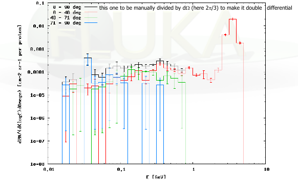
In the FLUKA course example I attached (the plot above), the angular bins used for scoring are not equal in solid angle width — for instance, the bins are 0–48°, 48–71°, and 71–90°. This suggests that we can score in multiple angular bins, but their solid angle widths can differ.
My question is: Can we define multiple angular bins with equal angle intervals (e.g., 0–15°, 15–30°, 30–45°, etc.) in FLUKA using USRBDX?
For example, I tried using linear multiple binning the bin width in sum.lis file was 0–23°, 23–41°, 41–59°, etc. — in this case, what should be done to obtain consistent results?
The plot that you are showing represents linear bins in solid angle, but NOT in polar angle. It is exactly what I was trying to explain. This plot has 3 bins between 0 and 2 * pi in solid angle. If you take the equation which links the solid angle omega with the polar angle theta
omega = 2*pi * (1-cos(theta))
you will see that the bins that, as mentioned in the plot legend, do not have the same width in polar angle, but actually have the same width in solid angle.
Let me try to explain again, a process which is fully symmetric in polar angle theta will not yield the same number of particles in equally spaced bins in theta when we are in 3 dimensional space. Therefore, the binning that you can define in USRBDX is by default not in theta, but you can extract all the information from the sum.lis file (as explained in the previous post)