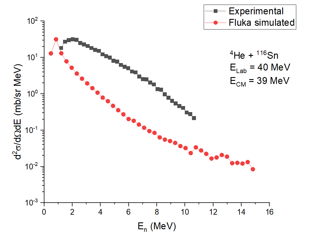
I tried to reproduce the figure 1 b using FLUKA. Following were the beam and target condition:
40 MeV (lab frame) alpha with 116Sn target which will lead to a cm frame energy of 39 MeV. The residue will be 119Te in 1n reaction channel.
The double differential sigma plot was scored for backward direction (150 degree) with a 3 degree angular interval in each side.
The results show significant difference between experiment and simulation (almost 8 to 10 order , even more in some places).
The paper indicated that significant ground state deformation is observed for the residue 119Te. This can influence the neutron production. Is this already modeled in FLUKA ?
I tried with Sn 124 as target for which the ground state deformation is very small. In that case also, the difference between experiment and simulation was 10 times or more.
I am attaching the journal paper as well as simulation.
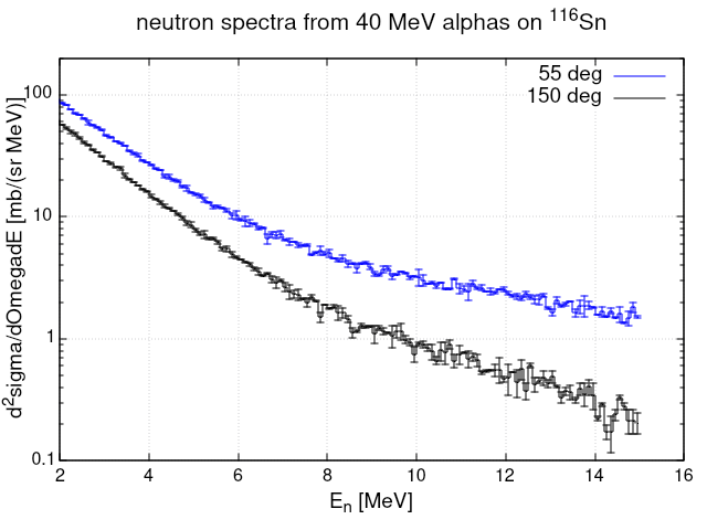
Emitted neutrons were detected using four liquid scintillator based neutron detectors of dimensions 5" × 5" placed at the laboratory angles of 55, 120, 135, and 150 deg at a distance of 1.5 m from the target.
These are lab angles, not CM angles. Correct your USRYIELD cards accordingly and you should get the following result:
I have changed the usryield setting with Polar theta lab. But now the values are all very much below 10. Have you changed any other parameter? Or have you put CM angles in usryield after converting the lab angle to CM angle to get the above plot ?
Forget about CM angles and remember instead that - in order to get the considered plot - the tab.lis results have to be divided by the reaction probability (about 1.9E-5 as in the already discussed Number of stars summary of the 00N.out output files) and multiplied by 1E-3 (to account for the /GeV to /MeV transformation of the double differential cross section unit).
Also, your 23 USRYIELD unit turns out to be identical to the 21 one because you did not change the angular interval.
Thank you @ceruttif for the useful conversion parameters, I totally forgot about them.
Apart from this, in general case, there exists a relationship of sigma (lab) and sigma (CM). Hence, is it not required to use CM frame angles, since in the plot mentioned in the report, the double differential sigma values are given for CM frame ?
Or will it not matter since in double differential form, the numerator (sigma) and the denominator (omega) are both either in lab or CM frame i.e. the graph will be same if we use Polar theta lab degree = 150 or polar theta CM degree = appropriate conversion of 150 degree lab to CM ?
Is it the case?
Also, as it is mentioned in the report that, the TALYS plots were given considering pre-equilibrium decay mode and then compound + pre-equilibrium decay mode. Is it possible to do such filtering in FLUKA ? For e.g. as they quoted Fig. 1(b) shows that the backward angle data can be reproduced well with the mode (2) alone, whereas both the modes are required to explain the forward angle data. Can we make such observation using FLUKA also ?
As mentioned above, angles in the paper appear to be in the lab, so further CM considerations may be moot (I have however not done a full cursory check of the rest of the paper).
For the sake of completeness:
Apart from this, in general case, there exists a relationship of sigma (lab) and sigma (CM). Hence, is it not required to use CM frame angles, since in the plot mentioned in the report, the double differential sigma values are given for CM frame ?
First of all the conversion from lab and CM scattering angles is unique only when the projectile (or ejectile 1 in general) is lighter than the target (ejectile 2 in general), which is your case here, but be careful with these logics as it is prone to trouble.
Then you are deliberately forgetting the fact that when performing a change of variables it’s not just a matter of scaling the horizontal axis: there is a Jacobian in between which accordingly reshapes the distribution (and this is physical!).
i.e. the graph will be same if we use Polar theta lab degree = 150 or polar theta CM degree = appropriate conversion of 150 degree lab to CM ?
No for the same reason. And furthermore, differential cross sections are generally not Lorentz invariant (except for carefully chosen variables), so if you change frame you must expect different shapes.
Such filtering is not directly accessible to users. On the other hand, the related effort is not really justified in view of the obviousness of the observation, which does not require FLUKA to be proved, rather any good nuclear reaction book.
I understood the intricacy of using lab frame and CM frame parameters. I enquired the author, and they informed that although the angles are mentioned as lab angles in the paper, the double differential plot is done for CM system since in nuclear physics studies, they are interested with CM frame observation. I will look into how the authors have made those conversion so that there won’t be discrepancy in the simulation and experiment as far as the technique is considered.
Thank you both once again for the explanation.
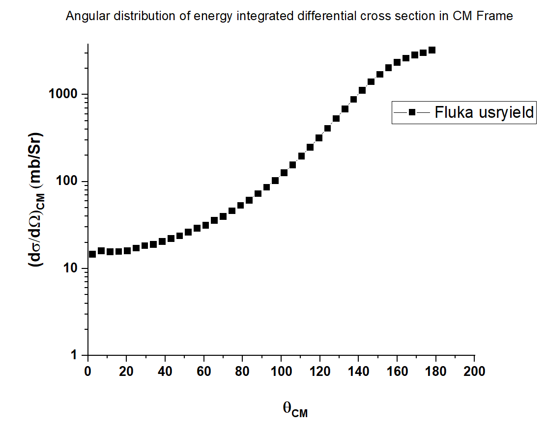
I have scored another quantity d(sigma)/d (omega) in CM frame with CM polar angle. I expected the plot to be some what symmetrical around 90 degree in both sides, but the present plot does not seem right. I have multipled the tab lis values by the energy interval i.e. 0.015 GeV and then divided it by total no of stars 1.88E-5.
Also I have converted the radian value in horizontal axis to degree values.
CM scoring cannot apply to your case. In the absence of an additional USRYIELD card with SDUM=BEAMDEF setting the CM frame (but inapplicable to a nucleus target), a proton is taken as default target to this purpose, explaining your findings, which by the way are not at all supposed to be symmetrical around 90 deg, since the two-body system is asymmetrical.