Dear Abdul,
I had figured out rest of the things.
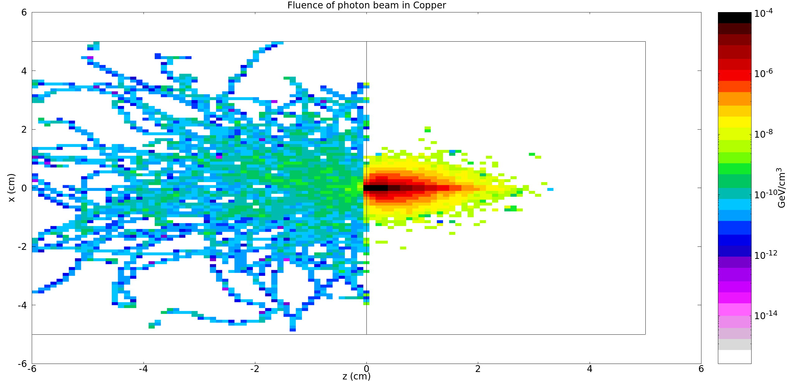
Indeed, looks like the lack of intensity in your BEAMPART related spectra in your original post is simply due to the fact that the photons that are emitted from the target into air are secondary photons. These most likely come from Compton scattering (or may even be fluorescence photons after Compton scattering itself or photoelectric events).
Now I just need opinion that if the method to record the backscattered photons used in the input files is correct or not?
(NB: they will not be “backscattered” photons, but secondary photons emitted in the backward direction exiting the target. Being terribly/needlessly picky, photons don’t “scatter”: they are either absorbed, emitted, or transported - but one tolerates expressions a la “Compton/Rayleigh scattering” with this implicit understanding.)
Your USRBDX card looks alright, provided you want the current of photons from target to air. Your min and max energy values are the default of 0 and beam energy, respectively, so that’s also OK.
In your USRYIELD card, instead, it may be wise to score the yield (dN/dx1dx2) instead of the cross section, considering that you have a thick target.
And if I use mgdraw routine with BXDRAW subrogation to record the begging and final position, using Xtrack(0) amd Xtrack(1) respectively, energy etrack-am(jtrack), and direction of cosines then the output results will depict the ones for the scattered photons from the target?
With your mgdraw.f, entry BXDRAW, you are writing out information for all particles crossing the boundary between the target and air, as per
      IF ( (MREG == 4) .AND. (NEWREG == 3) ) THEN
         WRITE (99, * )  JTRACK, XTRACK(0),YTRACK(0),ZTRACK(0), CXTRCK, CYTRCK,
     &   CZTRCK, (ETRACK-AM(JTRACK)), XTRACK(1),YTRACK(1),ZTRACK(1)
      END IF
In your simulation you shall have both electrons (JTRACK=3) and photons (JTRACK=7) triggering this write-out. We assume you are filtering out the photons in your custom post-processing. If not, you need a further condition (JTRACK==7) in your logics.
While at it, a few details:
-
in your BXDRAW entry, you may readily use the XSCO,YSCO,ZSCO variables to print the boundary crossing position. These indeed match XTRACK(1),YTRACK(1),ZTRACK(1) (end of step position on the boundary).
-
We do not believe you need the XTRACK(0),YTRACK(0),ZTRACK(0), reporting the beginning of the boundary crossing step - feel free to remove them unless you have good reason to write them out for your analysis.
-
Small (but confusing) detail: the header of your *_BXDRAW_data file does not match the content. You may want to adapt it accordingly.
Cheers,
Alexandra and Cesc