Dear experts,
I am irradiating water by electrons of energy 2 MeV (pencil beam).
I want to reduce the radiation outside the irradiation room to 0.02 ms/hr (milisievert/hour as per the safety limits).
the geometry is given in the attached input file.
I have few questions:
for radiation calculation, I am using usrbin (with DOSE-EQ) by region. I am then multiplying the answer by total no. of electrons as per the beam current (40 mA) and by 3600 (1 hour) and dividing by volume (SIDERM). Is it correct for getting dose-eq rate ?
for dose calculation in water, I am using usrbin (with Energy) by region (for water region). then I am multiplying the answer by beam current and with time of irradiation and dividing by the volume and density of water region. Is it correct ? will I need to add other things in input file (like physics card etc.) to get more precise results or the input file is fine ?
For the geometry in attached input file, to reduce the dose-eq rate outside the room (I want radiation calculation in the region VOISIDE), when I am increasing the concrete wall thickness, after a particular thickness (464630) I am getting a sharp drop to zero value. why this is happening ? while for the thickness of 454530, the value is 0.00444817 ps/pri or 385837 s/hr
If instead of using only concrete, I am choosing a stainless steel wall (8 cm thick along sidewalls and 7 cm thick along roof) and then concrete wall (30 cm thick along all sides), I am getting Dose-Eq (0.000477218 psv/pri or 41610 s/hr). after this when I am increasing the thickness of concrete by 1 cm, I am getting sharp decrease to zero value.
I am really unable to understand why this is happening. if we can go upto 0.000477218 by using steel, why we cannot get this value by increasing thickness of concrete only?
4) Do I need to use EMFCUT cards for each region (transport) and material (prodcut).
Dear Anjali,
thanks for your question.
1 - For your type of problem I would suggest you to use a mesh scoring and not a region one because with 2D plots you can easily identify possible hot-spots. Mind that the normalization constant for mesh scoring is just beam current / electron charge (which gives you the number of electrons per second): this will give you the prompt dose in pSv/s. Mind that also for region scoring the normalization constant is beam current / electron charge / volume.
DOSE-EQ scores by default ambient dose equivalent using data from ICRP74 and Pelliccioni: for photons below few tens of keV ambient dose is not very conservative but it should not matter behind your shield.
You can use the AUXSCORE card if you need to change the coefficients (EWTMP is the most conservative)
2 - If you score ENERGY you are scoring energy density. I assume you wanted to calculate the dose (energy per unit mass) delivered to the target during full irradiation so you can score DOSE: for a region type scoring the normalization constant to have the result in Gy is beam current / electron charge * irradiation time / volume * 1.602176462E-7 (latter factor is needed to convert GeV/g, which is the default unit, to Gy/g, see USRBIN).
3 - Redo the normalization and add some Cartesian USRBINs to score particle fluences and not only dose/energy: you can understand much better the attenuation.
4 - Yes, if you want threshold different from the defaults: prod-cut is material based (you can do from BLCKHOLE to @LASTMAT so no need to set manually for every material) while transport is region based (you can do from BLKBODY to @LASTREG so again no need to set manually for all the regions). It’s simpler if you set the thresholds as kinetic energies (10keV for e+/e- and 1keV for photons is more than enough)
many thanks @dbozzato
all you said about normalization, mesh scoring, Dose calculation, using auxscore card to change the coefficient and about the transport and prodcut is copied.
But I am still not getting how to find the total radiation outside as (I guess) this quantity will decide what should be the thickness of shielding room.
How will I get total radiation by 2D mesh scoring ? is there anything that I need to do manually with data that I will get in 2D mesh scoring for total dose-eq rate in specified region ?
Dear Anjali,
I would say that the thickness of the shielding should be optimized by looking at the maximum prompt dose rate, not by an integral over a region. This is why I suggested in the first place to score over a mesh and not by region since in the latter case (properly normalized) you would have an average/global value which is lower than the maximum values that you could have locally.
To view your results you can either make 2D plots in Flair in the Plot tab or, always using the results from your scoring, make a 1D plot selecting a specific projection. You can find detailed explanation and some examples in the course lecture on scorings and the related exercise.
Do not hesitate to ask if you need help with that or if you have further questions.
Dear Junjie Zhang
beam intensity will be current x time/ charge on electron, so for 1A current and time 1 sec, beam intensity will be 6.25e18.
so many thanks @dbozzato
Now I understood the concept fully. From usrbin (DOSE-EQ) 2D distribution, I will get the hotspots then in that direction by using 1D plot I will get the required quantity (locally) after normalization.
So will it be right if I set the no. of bins ( binwidth will become 10 cm ) so that the number of data points will be less and according to the values I then choose the shielding thickness. for Ex. if binwidth is choosen to be 16 cm in X and Y and 20 cm along Z (by setting no. of bins). then normalizing the value obtained in the mesh (region by choosing proper projection) by multiplying current x time /charge.
this normalized quantity will be dose-eq rate and as per the requirement I will change the thickness of shield.
Dear Anjali,
yes it’s correct. You can do the normalization (both for 2D and 1D plots) specifying the normalization factor in the Norm field of the Flair Plot tab.
You can choose/optimize the bin width according to the size of the output and statistical uncertainty of In general larger bins would give a more granular result, too fine binning requires higher number of primaries to reach convergence and have meaningful results with good statistics (provided transport settings are apt to the problem).
so many thanks @horvathd
after the suggestions from dbozzato, I understood many things including the need to look for hotspots, maximum prompt dose rate and fluence scoring very nicely.
this is the input file. only_concrete.inp (4.7 KB)
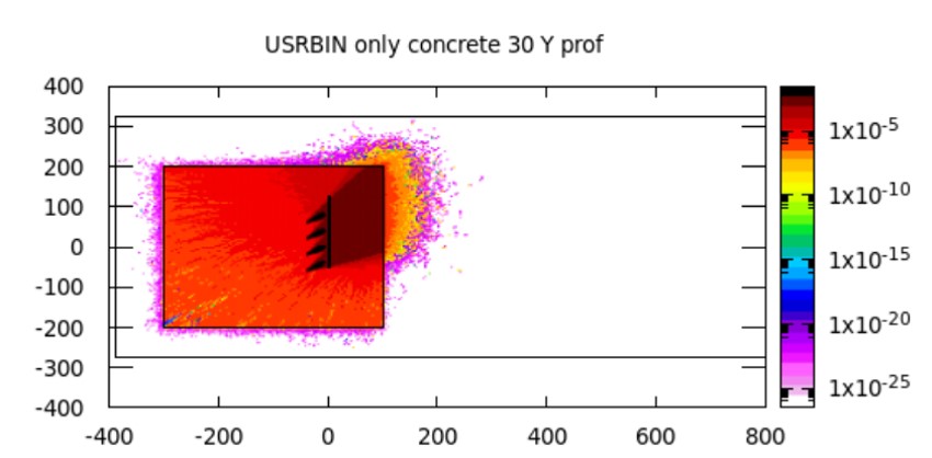
with 2D distribution, logarithmic scale shows that lower value that we can go for is 1e-20 - 1e-25 (psv/pr)
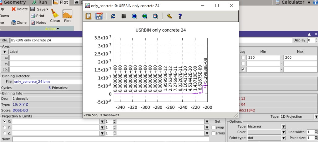
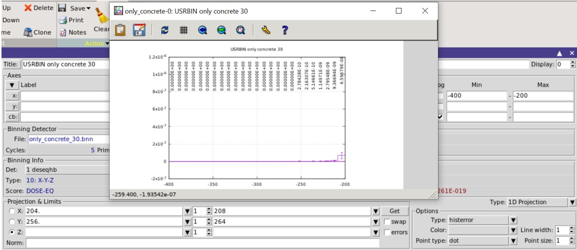
but with 1D, with near about projections, without projections and also if Y axis scale chosen to be logarithmic, the values are dropping to zero after 1e-12 (psv/pr). why the values are not going to smaller values as like 2D
is there anything that I am missing in my input or in the output interpretation?
or the shielding thickness considered in geometry is enough as if the dimension for concrete is increased, dose-eq is reducing to zero (psv/pr) ?
I want to reduce the radiation out side the shielding to less than 0.1 msv/hr. on normalizing the result of 1e-12 (psv/pr) order, with current of 1A, (1e-12 x 1e-12 x 3600 x 1/ 1.6 x 1e-19) I am getting ~ 22.5 msv/hr. So should I consider that radiation is reducing to zero with the geometry in input ?
Thanks in advance …
Dear Anjali,
could you please share your flair project as well so that I can reconstruct more easily what you have plotted (i.e. ranges)?
Many thanks,
Davide
Dear Anjali,
many thanks for the files.I had a look at your flair project and my advice would be the following.
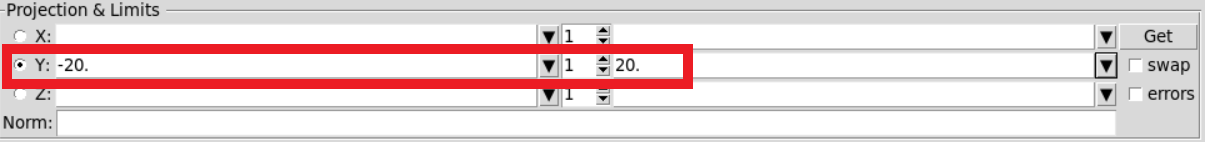
When you do a 2D plot, you should specify a range for the averaging otherwise flair will plot the average value along the selected direction. For example, if you select Y but you don’t specify any value, the 2D map in X and Z will be the average over the full range of Y (average that will be lower than local maxima)
The normalization can be entered in the Norm field as the above picture.
The averaging range that you enter has to be meaningful to the case. In the example, -20:20 could be reasonable considering your beam extension. For the 1D projections, the range you select is far too large for you to extract information about the dose above the roof or laterally. For the record, when you do the 1D plot, to have the logarithmic scale on the vertical axis you should tick Log for y, not cb (the latter is used only for color bars)
The fact that you score zero it does not mean that the radiation is zero. If you have a look at the statistical uncertainty of your results (click on errors and remove the log scale), you will see that with the only exceptions of the points around the primary beam, it is higher than 40%, which is not that good. You should definitely increase the number of primaries and cycles (with your current settings it runs for less than 5 minutes) and possibly reduce the size of the bins: having bins of approx 4x4x4cm^3 or 8x8x10cm^3 is not necessary if you then make projections selecting wider ranges. Maybe 10x10x10cm^3 or 20x20x20cm^3 would be better and the convergence would be faster.
Once you are confident with the changes you could have a look at biasing techniques which are often employed in shielding calculations.
thanks a lot @dbozzato
all your suggestions were really helpful, I tried with increased number of primaries, also by reducing the bin size and found that zero values (obtained with earlier case) doesn’t mean zero radiation (zero value was due to statistics problem).
So I tried with biasing. For biasing I have used Biasing card only_concrete_biasinglayers.inp (4.7 KB)
For this I first tried by giving importance to regions like to water:100, STLTRY:500, AIRIN:2500, CONCRETE: 12500, VOID: 62500 (with no layers in CONCRETE region in the geometry)
with this I got no much difference in the dose-eq distribution(without biasing).
But when I defined the layers in CONCRETE region as given in the attached input file, for same number of primaries I am getting good distribution and also the results as per requirement (with 1e06 primaries in start card and 30 cycles, in three cores (spawn) = 90x1e06 primaries). But I want to know that I am applying the biasing in right way ?
also I tried with EMF-BIAS (LPBEMF). But I did not got how to define it like do I need to define one card for each region with different energy?
Do I need to use EMF-BIAS (LPBEMF or other) or biasing card is also right to use ?
Thanks in Advance …
Dear Anjali,
Region importance biasing is the easiest to implement and control and, as you have seen, it does the trick. EMF-BIAS sets electron and photon special biasing parameters and requires some experience and some trials to tune it.
You have implemented correctly. Keep in mind that what is important for FLUKA, is the ratio of the importances of two adjacent regions: this ratio should be in the range 0.2 - 5: for example, for the particles travelling from CONCREA1 to GND or CONCREA2 to GND the ratio of the importances will be 5 anyway.
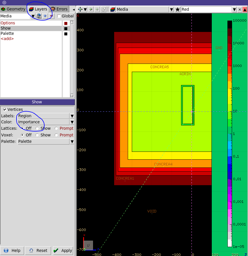
You can always visualize the importance that you have assigned in the Flair Geometry tab. If needed you can segment GND as done for the other region